Mars rover
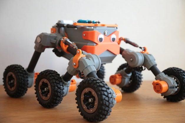
After six months I have finished Mars Rover project and build one on my own. It is based on other project that was published on thingiverse. However, I have made few improvements on mechanical part and made my own electronic control module for this RC vehicle.
One of the very first tests with a regular RC remote controller just to see if mechanics are ok.
Second video with completely finished hardware and testing the bluetooth communication with tablet.
Overall performance
At first I thought it will be uncomfortable to steer this vehicle with digital joystick, but it turned out that it is actually quite easy and fun.
Bluetooth communication is super good. Farthest distance I tested was around 70 meters and it was still as responsive as from close distance with no sensible lag.
Controller battery is ~4000 mAh and controller board draws around 200 mA so the math is simple - theoretically it should last 20h with one charge. Motor battery is 6000 mAh but with high C which isn’t actually necessary to be super high as I found out. So probably it’s possible to find battery with same form factor, lower C but higher amperage so that it lasts longer. The current drawn by motors varies a lot. So does the time how long it lasts with one charge. On a flat surface where it can drive freely it consumes just like 500 mA on all six motors together. So the motor battery shouldn’t be changed more often then once every four hours at intense driving. Didn’t had time to do real tests on battery discharge times.
Mechanics
I didn’t like the idea of axle going all the way through the vehicle body so I lasercut those (axle_attachment.dxf) circles from 3mm plywood. Now those circles are mounted to vehicle body with six smaller bolts and axle bolts are attached there with two nuts, one from each side and tightened together.
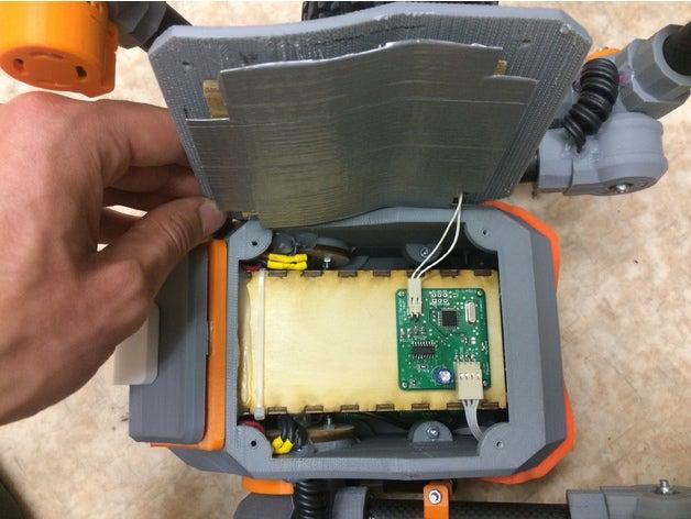
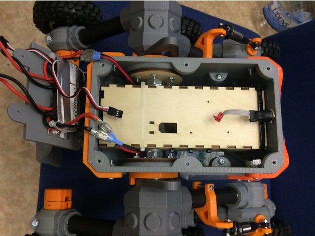
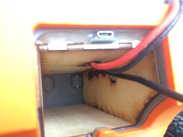
Also I wanted rover to have a battery compartment for easy battery installing/changing etc. so I designed (battery_compartment.dxf) “box” which fits perfectly inside rover main frame. This also has to be cut out from 3mm plywood. Probably you’ll have to adjust width of its “fingers”, because the kerf of your lasercutter may vary from the one I have access to.
I also modified one of the 3D parts. Originally (by repbaza) it was named as 10.stl. I used these ESC for motor driving and I wanted to mount them to this part. In that case they take so little space and their heat sinks make rover cooler. Both literally and from the looks. The bottom part which holds those ESC had to be as thin as possible so I just made it from scrap (comes from LCD monitor) aluminium sheet.
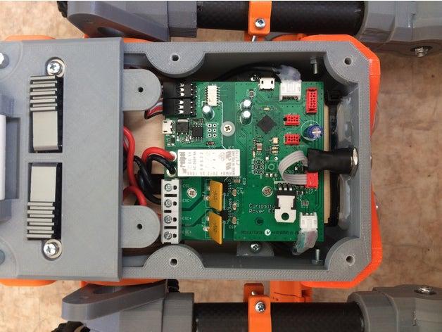
Electronics
Task was to design electronics which would:
❉ communicate to tablet via Bluetooth;
❉ control ESC’s;
❉ monitor charge status of both batteries;
❉ monitor power consumption of drive battery;
❉ read RFID tags from 15cm distance;
❉ have possibility to cut off power for ESC’s and also control module itself if necessary;
❉ have electrically isolated power sources for control module and motor ESC’s to minimise interference from motors.
So I designed two PCB’s - one just for RFID reading and other for everything else. They use UART communication between each other. Good thing is that now this RFID reader part may be considered as a separate module and can be replaced by anything else, because it has 5V power source and serial communication with main controller board. For example - moving arm, infrared sensor, videocamera, GPS etc. And if using RS-485 for communication then even all of them can be connected at the same time.
It uses “powerbank” as power source for controller. I did a small modification for power bank so that now usb data lines are used for battery discharge monitoring. So no complicated connectors are necessary - just plug the USB connector. Also charging is simple, just as for any other power bank. For powering the motors I used this hobbyking battery. Another good thing about having two power sources is that when motor battery is empty, vehicle doesn’t loose connection with tablet and can indicate that the motor battery has to be changed and, for example, it’s location if it has GPS.
USB micro socket at rear end under the lid for easy firmware programming without need to open any covers.
I attached image of ECU schematic. If interested, you can have a glimpse of what is going on on that main PCB. Probably some of you will notice that I placed Arduino Micro PCB design in the middle of my PCB. There is one mistake made by my inattention - I forget to connect relay to 5V power line, but it was really simple to solder a jumper wire there, because power line is going right along by the relay coil contacts.